SECTION 140.4 – PRESCRIPTIVE REQUIREMENTS FOR SPACE CONDITIONING SYSTEMS
A building complies with this section by being designed with and having constructed and installed a space-conditioning system that meets the applicable prescriptive requirements of Subsections (a) through (q).
Single zone space conditioning systems with direct expansion cooling with rated cooling capacity 240,000 Btu/hr or less serving the following spaces shall meet the applicable requirements in A-H, or shall meet the performance compliance requirements of Section 140.1. All other system types, including systems with rated cooling capacity greater than 240,000 Btu/hr, multi-zone systems, and systems using central boilers or chillers, shall comply with the applicable requirements of Section 140.
A. Retail and grocery
building spaces in Climate Zones 2 through 15. The
space-conditioning system shall be a heat pump.
B. Retail and grocery
building spaces in
Climate Zones 1 and 16 with cooling capacity less than 65,000 Btu/hr. The
space-conditioning system shall be an air conditioner with furnace.
C. Retail and Grocery
Building Spaces in
climate zones 1 and 16 with cooling capacity 65,000 Btu/hr or greater. The space conditioning system shall be a dual-fuel heat pump.
D. School Building Spaces.
For climate zones 2 through 15, the space conditioning system shall be a heat pump. For Climate Zones 1 and 16, the space-conditioning system shall be a dual-fuel heat pump.
E. Office, Financial Institution, and Library Building Spaces in
Climate Zones 1 through 15. The
space-conditioning system shall be
a heat pump.
F. Office, financial institution, an
d library building spaces in Climate Zone 16 with cooling capacity less than 65,000 Btu/hr. The space-conditioning system shall be an air conditioner with furnace.
G. Office, financial institution, an
d library building spaces in Climate Zone 16 with cooling capacity 65,000 Btu/hr or greater. The space-conditioning system shall be a dual-fuel heat pump.
H. Office spaces in warehouses. The
space-conditioning system shall be
a heat pump in all climate zones.
EXCEPTION to Section 140.4(a)2: Systems utilizing recovered heat for space heating.
In making equipment sizing calculations under Subsection (a), all of the following rules shall apply:
1. Heating and cooling loads. Heating and cooling system design loads shall be determined in accordance with the procedures described in Subsection A or B below:
A. For systems serving hotel/motel buildings, and nonresidential buildings other than healthcare facilities, the method in the 2017 ASHRAE Handbook, Fundamentals shall be used, or as specified in a method approved by the Commission.
B. For system serving
healthcare facilities the method in the California Mechanical Code shall be used.
2. Indoor design conditions. Indoor design temperature and humidity conditions for comfort applications shall be determined in accordance with Subsection A or B below:
A. For systems serving
hotel/motel buildings, and nonresidential buildings other than
healthcare facilities, ASHRAE Standard 55 or the 2017 ASHRAE Handbook, Fundamentals Volume, except that winter humidification and summer dehumidification shall not be required.
B. For system serving
healthcare facilities the method in the California Mechanical Code shall be used.
3. Outdoor design conditions. Outdoor
design conditions shall be selected in accordance with subsection A or B below:
A. For systems serving
hotel/motel buildings, and nonresidential buildings other than
healthcare facilities the
design conditions from Reference Joint Appendix
JA2 shall be used, which is based on data from the ASHRAE Climatic Data for Region X. Heating design temperatures shall be no lower than the Heating Winter Median of Extremes values. Cooling design temperatures shall be no greater than the 0.5 percent Cooling Dry Bulb and Mean Coincident Wet Bulb values.
B. For system serving
healthcare facilities the method in Section 320.0 of the California Mechanical Code shall be used.
EXCEPTION to Section 140.4(b)3: Cooling design temperatures for cooling towers shall be no greater than the 0.5 percent cooling design wet bulb values.
6. Lighting. Lighting heating and cooling loads shall be based on actual design lighting levels or power densities as specified in Section 140.6.
8. Process loads. Loads caused by a process shall be based upon actual information on the intended use of the
building.
9. Miscellaneous equipment. Equipment loads other tha
n process loads shall be calculated using design data compiled from one or more of the following sources:
A. Actual information based on the intended use of th
e building; or
B. Published data from manufacturer's technical publications or from technical societies, such as the ASHRAE Handbook, Applications Volume; or
C. Other data based on the designer's experience of expected loads and
occupancy patterns.
12. Other loads. Loads such as warm-up or cool-down shall be calculated from principles based on the thermal capacity of the
building and its contents, the degree of setback, and desired recovery time; or may be assumed to be no more than 30 percent for heating and 10 percent for cooling of the steady-state design loads. In addition, the steady-state load may include a safety factor in accordance with Section
140.4(b)11.
(c) Fan systems. Each fan system moving air into, out of or between conditioned spaces or circulating air for the purpose of conditioning air within a space shall meet the requirements of Items 1, 2 and 3 below.
For each fan system that includes at least one fan or fan array with fan electrical input power ≥ 1 kW, fan system electrical input power (Fan kWdesign,system) determined per Section 140.4(c)1(B) at the fan system design airflow shall not exceed Fan kWbudget as calculated per Section 140.4(c)1(A).
A. Calculation of Fan Power Budget (Fan kWbudget). For eac
h fan system:
i. Determine the
fan system airflow and choose the appropriate table(s) for fan power allowance.
b. For supply-only fan systems, use th
e fan system airflow and power allowances in
Table 140.4-A.
c. For relief fan systems, use the design relief airflow and the power allowances in
Table 140.4-B.
d. For exhaust, return and transfer fan systems, use th
e fan system airflow and the power allowances in
Table 140.4-B.
e. For complex fan systems, separately calculate the fan power allowance for the supply and return/exhaust systems and sum them. For the supply airflow, use supply airflow at the fan system design conditions, and the power allowances in
Table 140.4-A. For the return exhaust airflow, use return /exhaust airflow at the
fan system design conditions, and the power allowances in
Table 140.4-B.
ii. For each
fan system determine the components included in th
e fan system and sum the Fan Power Allowances of those components. All fan systems shall include the System Base Allowance. If, for a given component, only a portion of the
fan system airflow passes through the
component, calculate the Fan Power Allowance for tha
t component per Equation 140.4-A:
EQUATION 140.4-A FAN POWER ALLOWANCE
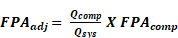
Where
FPAadj = The corrected fan power allowance for the component in w/cfm
Qcomp = The airflow through component in cfm
Qsys = The fan system airflow in cfm
FPAcomp = The fan power allowance of the component from Table 140.4A or Table 140.4B
iii. Multiply the
fan system airflow by the sum of the fan power allowances for the
fan system.
iv. Divide by 1000 to convert to Fan kW
budget.
v. For building sites at elevations greater than 3,000 feet, multiply Fan kW
budget by Correction Factor in
Table 140.4-C.
B. Determining
Fan System Electrical Input Power (Fan kW
design,system). Fan kW
design,system is the sum of Fan kWdesign for each fan or fan array included in the
fan system with Fan kW
design ≥ 1 kW. If variable speed drives are used, their efficiency losses shall be included. Fan input power shall be calculated with two times the clean filter pressure drop, which is the mean of the clean filter pressure drop and design final filter pressure drop. The Fan kW
design for each fan or fan array shall be determined using one of the following methods. There is no requirement to use the same method for all fans in a
fan system:
i. Use the default Fan kW
design in
Table 140.4-D for one or more of the fans. This method cannot be used for complex fan systems.
ii. Use the Fan kW
design at fan system design conditions provided by the manufacturer of the fan, fan array, or equipment that includes the fan or fan array calculated per a test procedure included in USDOE 10 CFR Part 430, USDOE 10 CFR Part 431, ANSI/AMCA Standard 208-2018,
ANSI/AMCA Standard 210-2016, AHRI Standard 430-2020,
AHRI Standard 440-2019, or ISO 5801-2017.
iii. Use the Fan kW
design provided by the manufacturer, calculated a
t fan system design conditions per one of the methods listed in Section 5.3 of ANSI/AMCA 208-2018.
iv. Determine the Fan kW
design by using the maximum electrical input power provided on the motor nameplate.
|
Airflow
|
Multi-Zone VAV Systems
≤5,000 cfm1
|
Multi-Zone VAV Systems >5,000 and ≤10,000 cfm1
|
Multi-Zone VAV Systems >10,000 cfm1
|
All Other Fan Systems ≤5,000 cfm
|
All Other Fan
Systems >5,000 and ≤10,000 cfm
|
All Other Fan Systems>10,000 cfm
|
|
Supply System Base Allowance for AHU serving spaces ≤ 6 floors away).
|
0.395
|
0.453
|
0.413
|
0.232
|
0.256
|
0.236
|
|
Supply system base allowance for AHU serving spaces > 6 floors away
|
0.508
|
0.548
|
0.501
|
0.349
|
0.356
|
0.325
|
|
MERV 13 to MERV 16 Filter upstream of thermal conditioning equipment (two times the clean filter pressure drop)2
|
0.136
|
0.114
|
0.105
|
0.139
|
0.120
|
0.107
|
|
MERV 13 to MERV 16 Final filter downstream of thermal conditioning equipment. ( two times the clean filter pressure drop)2
|
0.225
|
0.188
|
0.176
|
0.231
|
0.197
|
0.177
|
|
Filtration allowance for > MERV 16 or HEPA Filter ( two times the clean filter pressure drop)2
|
0.335
|
0.280
|
0.265
|
0.342
|
0.292
|
0.264
|
|
Central Hydronic heating coil allowance
|
0.046
|
0.048
|
0.052
|
0.046
|
0.050
|
0.054
|
|
Electric heat allowance
|
0.046
|
0.038
|
0.035
|
0.046
|
0.040
|
0.036
|
|
Gas heat allowance
|
0.069
|
0.057
|
0.070
|
0.058
|
0.060
|
0.072
|
|
Hydronic/DX cooling coil or heat pump coil (wet) allowance3
|
0.135
|
0.114
|
0.105
|
0.139
|
0.120
|
0.107
|
|
Solid or liquid Desiccant system allowance
|
0.157
|
0.132
|
0.123
|
0.163
|
0.139
|
0.124
|
|
Reheat Coil for Dehumidification Allowance
|
0.045
|
0.038
|
0.035
|
0.046
|
0.040
|
0.036
|
|
Allowance for Evaporative humidifier/cooler in series with a cooling coil. Value shown is allowed watts/cfm per 1.0 Inches of water gauge (in.w.g.) Determine pressure loss (in.w.g.) at 400 fpm or maximum velocity allowed by the manufacturer, whichever is less. [Calculation required, see note 4]
|
0.224
|
0.188
|
0.176
|
0.231
|
0.197
|
0.177
|
|
Allowance for 100% Outdoor air system5.
|
0.000
|
0.000
|
0.000
|
0.070
|
0.100
|
0.107
|
|
Energy recovery allowance for 0.50 ≤ ERR <0.556
|
0.135
|
0.114
|
0.105
|
0.139
|
0.120
|
0.107
|
|
Energy recovery allowance for 0.55 ≤ ERR <0.606
|
0.160
|
0.134
|
0.124
|
0.165
|
0.141
|
0.126
|
|
Energy recovery allowance for 0.60 ≤ ERR <0.656
|
0.184
|
0.155
|
0.144
|
0.190
|
0.163
|
0.146
|
|
Energy recovery allowance for 0.65 ≤ ERR <0.706
|
0.208
|
0.175
|
0.163
|
0.215
|
0.184
|
0.165
|
|
Energy recovery allowance for 0.70 ≤ ERR <0.756
|
0.232
|
0.196
|
0.183
|
0.240
|
0.205
|
0.184
|
|
Energy recovery allowance for 0.75 ≤ ERR <0.806
|
0.257
|
0.216
|
0.202
|
0.264
|
0.226
|
0.203
|
|
Energy recovery allowance for ERR ≥ 0.806
|
0.281
|
0.236
|
0.222
|
0.289
|
0.247
|
0.222
|
|
Coil Runaround Loop
|
0.135
|
0.114
|
0.105
|
0.139
|
0.120
|
0.107
|
|
Allowance for Gas phase filtration. Value shown is allowed w/cfm per 1.0 in. wg air pressure drop. [Calculation required, see note 4]
|
0.224
|
0.188
|
0.176
|
0.231
|
0.197
|
0.177
|
|
Economizer Return Damper
|
0.045
|
0.038
|
0.035
|
0.046
|
0.040
|
0.036
|
|
Air blender allowance
|
0.045
|
0.038
|
0.035
|
0.046
|
0.040
|
0.036
|
|
Sound attenuation section [fans serving spaces with design background noise goals below NC35]
|
0.034
|
0.029
|
0.026
|
0.035
|
0.030
|
0.027
|
|
Deduction for systems that feed a terminal unit with a fan with electrical input power < 1kW
|
-0.100
|
-0.100
|
-0.100
|
-0.100
|
-0.100
|
-0.100
|
|
Low-turndown single-zone VAV fan systems meeting the requirements in note 7.
|
0.000
|
0.000
|
0.000
|
0.070
|
0.100
|
0.089
|
Footnotes to Table 140.4-A
1. See Section 100.1 for the definition of FAN SYSTEM, MULTI-ZONE VARIABLE AIR VOLUME (VAV).
2. Filter fan power allowance can only be counted once per fan system, except fan systems in healthcare facilities, which can claim one of the MERV 13 to 16 filter allowances and the HEPA filter allowance if both are included in the fan system.
3. Healthcare facilities can claim this fan power allowance twice per fan system where coil design leaving air temperature is less than 44 ⁰F.
4. Power allowance requires further calculation by multiplying the actual inches of water gauge (in.w.g.) of the device/ component by the watts/ cfm in Table 140.4-A.
5. The 100% outdoor air system must serve 3 or more HVAC zones and airflow during non-economizer operating periods must not exceed 135% of minimum requirements in Section 120.1(c)3
6. Enthalpy Recovery Ratio (ERR) calculated per ANSI/ASHRAE 84-2020.
7. A low-turndown single-zone VAV fan system must be capable of and configured to reduce airflow to 50 percent of design airflow and use no more than 30 percent of the design wattage at that airflow. No more than 10 percent of the design load served by the equipment shall have fixed loads.
|
Airflow
|
Multi-Zone VAV Systems1 ≤5,000 cfm
|
Multi-Zone VAV Systems1 >5,000 and ≤10,000 cfm
|
Multi-Zone VAV Systems1 >10,000 cfm
|
All Other Fan Systems ≤5,000 cfm
|
All Other Fan Systems >5,000 and ≤10,000 cfm
|
All Other Fan Systems >10,000 cfm
|
|
Exhaust System Base Allowance
|
0.221
|
0.246
|
0.236
|
0.186
|
0.184
|
0.190
|
|
Filter (any MERV value)2
|
0.046
|
0.041
|
0.036
|
0.046
|
0.041
|
0.035
|
|
Energy Recovery Allowance For 0.50 ≤ ERR <0.55 3
|
0.139
|
0.120
|
0.107
|
0.139
|
0.123
|
0.109
|
|
Energy Recovery Allowance For 0.55 ≤ ERR <0.60 3
|
0.165
|
0.142
|
0.126
|
0.165
|
0.144
|
0.128
|
|
Energy Recovery Allowance For 0.60 ≤ ERR <0.65 3
|
0.190
|
0.163
|
0.146
|
0.191
|
0.166
|
0.148
|
|
Energy Recovery Allowance For 0.65 ≤ ERR <0.70 3
|
0.215
|
0.184
|
0.165
|
0.216
|
0.188
|
0.167
|
|
Energy Recovery Allowance For 0.70 ≤ ERR <0.75 3
|
0.240
|
0.206
|
0.184
|
0.241
|
0.209
|
0.186
|
|
Energy Recovery Allowance For 0.75 ≤ ERR <0.80 3
|
0.265
|
0.227
|
0.203
|
0.266
|
0.231
|
0.205
|
|
Energy Recovery Allowance For ERR ≥ 0.80 3
|
0.289
|
0.248
|
0.222
|
0.291
|
0.252
|
0.225
|
|
Coil Runaround Loop
|
0.139
|
0.120
|
0.107
|
0.139
|
0.123
|
0.109
|
|
Return or exhaust systems required by code or accreditation standards to be fully ducted, or systems required to maintain air pressure differentials between adjacent rooms
|
0.116
|
0.100
|
0.089
|
0.116
|
0.102
|
0.091
|
|
Return and/or exhaust airflow control devices required for space pressurization control
|
0.116
|
0.100
|
0.089
|
0.116
|
0.102
|
0.091
|
|
Laboratory and vivarium exhaust systems in high-rise buildings for vertical duct exceeding 75 ft. Value shown is allowed w/cfm per 0.25 in. wg for each 100 feet exceeding 75 feet. [Calculation required, see note 4]
|
0.058
|
0.051
|
0.045
|
0.058
|
0.052
|
0.046
|
|
Biosafety cabinet. Value shown is allowed w/cfm per 1.0 in. wg air pressure drop. [Calculation required, see note 4]
|
0.231
|
0.198
|
0.177
|
0.232
|
0.202
|
0.179
|
|
Exhaust filters, scrubbers, or other exhaust treatment required by code or standard. Value shown is allowed w/cfm per 1.0 in. wg air pressure drop. [Calculation required, see note 4]
|
0.231
|
0.198
|
0.177
|
0.232
|
0.202
|
0.179
|
|
Healthcare facility allowance5
|
0.231
|
0.198
|
0.177
|
0.232
|
0.202
|
0.179
|
|
Sound attenuation section [Fans serving spaces with design background noise goals below NC35.]
|
0.035
|
0.030
|
0.027
|
0.035
|
0.031
|
0.028
|
Footnotes to Table 140.4-B
1. See FAN SYSTEM, MULTI-ZONE VARIABLE AIR VOLUME (VAV) in definitions for Multizone to be classified as a Multi-Zone VAV System.
2. Filter pressure loss can only be counted once per fan system.
3. Enthalpy Recovery Ratio (ERR) calculated per ANSI/ASHRAE 84-2020.
4. Power allowance requires further calculation, multiplying the actual pressure drop (in. wg.) of the device/ component by the watts/cfm in the Table 140.4-B.
5. This allowance can only be taken for healthcare facilities.
TABLE 140.4-C AIR DENSITY CORRECTION FACTORS
|
Altitude (ft)
|
Correction Factor
|
|
<3,000
|
1.000
|
|
≥3,000 and <4,000
|
0.896
|
|
≥4,000 and <5,000
|
0.864
|
|
≥5,000 and <6,000
|
0.832
|
|
≥6,000
|
0.801
|
|
Motor Nameplate HP
|
Default Fan kWdesign with variable speed drive (Fan kWdesign)
|
Default Fan kWdesign without variable speed drive(Fan kWdesign)
|
|
<1
|
0.96
|
0.89
|
|
≥1 and <1.5
|
1.38
|
1.29
|
|
≥1.5 and <2
|
1.84
|
1.72
|
|
≥2 and <3
|
2.73
|
2.57
|
|
≥3 and <5
|
4.38
|
4.17
|
|
≥5 and <7.5
|
6.43
|
6.15
|
|
≥7.5 and <10
|
8.46
|
8.13
|
|
≥10 and <15
|
12.47
|
12.03
|
|
≥15 and <20
|
16.55
|
16.04
|
|
≥20 and <25
|
20.58
|
19.92
|
|
≥25 and <30
|
24.59
|
23.77
|
|
≥30 and <40
|
32.74
|
31.70
|
|
≥40 and <50
|
40.71
|
39.46
|
|
≥50 and <60
|
48.50
|
47.10
|
|
≥60 and <75
|
60.45
|
58.87
|
|
≥75 and ≤100
|
80.40
|
78.17
|
Footnotes to TABLE 140.4-D:
1. This table cannot be used for Motor Nameplate Horsepower values greater than 100.
2. This table is to be used only with motors with a service factor ≤1.15. If the service factor is not provided, this table may not be used.
2. Variable air volume (VAV) systems.
A. Static pressure sensor location. Static pressure sensors used to control variable air volume fans shall be placed in a position such that the controller set point is no greater than one-third the total design fan static pressure, except for systems with zone reset control complying with Section
140.4(c)2B. If this results in the sensor being located downstream of any major duct split, multiple sensors shall be installed in each major branch with fan capacity controlled to satisfy the sensor furthest below its setpoint; and
B. Setpoint reset. For systems with direct digital control of individual zone boxes reporting to the central control panel, static pressure setpoints shall be reset based on the zone requiring the most pressure; i.e., the set point is reset lower until one zone damper is nearly wide open.
EXCEPTION 1 to Section 140.4(c)3: Motors in fan-coils and terminal units that operate only when providing heating to the space served.
EXCEPTION 2 to Section 140.4(c)3: Motors in space conditioning equipment certified under Section 110.1 or 110.2.
EXCEPTION to Section 140.4(c): Fan system power caused solely by process loads.
(d) Space-conditioning zone controls. Each space-conditioning zone shall have controls designed in accordance with 1 or 2:
1. Each space-conditioning zone shall have controls that prevent:
C. Simultaneous provisions of heating and cooling to the same zone, such as mixing or simultaneous supply of air that has been previously mechanically heated and air that has been previously cooled either by cooling equipment or by economizer systems; or
2. Zones served by variable air-volume systems that are designed and controlled to reduce, to a minimum, the volume of reheated, recooled, or mixed air are allowed only if the controls meet all of the following requirements:
A. For each zone with direct digital controls (DDC):
i. The volume of primary air that is reheated, recooled or mixed air supply shall not exceed the larger of:
a. 50 percent of the peak primary airflow; or
b. The design zone outdoor airflow rate as specified by Section
120.1(c)3.
ii. The volume of primary air in the deadband shall not exceed the design zone outdoor airflow rate as specified by Section
120.1(c)3.
iii. The first stage of heating consists of modulating the zone supply air temperature setpoint up to a maximum setpoint no higher than 95ºF while the airflow is maintained at the
deadband flow rate.
iv. The second stage of heating consists of modulating the airflow rate from the
deadband flow rate up to the heating maximum flow rate.
B. For each zone without DDC, the volume of primary air that is reheated, re-cooled, or mixed air supply shall not exceed the larger of the following:
i. 30 percent of the peak
primary airflow; or
ii. The design zone outdoor airflow rate as specified by Section
120.1(c)3.
EXCEPTION 1 to Section 140.4(d): Zones with special pressurization relationships or cross-contamination control needs.
EXCEPTION 2 to Section 140.4(d): Zones served by space-conditioning systems in which at least 75 percent of the energy for reheating, or providing warm air in mixing systems, is provided from a site-recovered or site-solar energy source.
EXCEPTION 3 to Section 140.4(d): Zones in which specific humidity levels are required to satisfy exempt process loads. Computer rooms or other spaces where the only process load is from IT equipment may not use this exception.
EXCEPTION 4 to Section 140.4(d): Zones with a peak supply-air quantity of 300 cfm or less.
EXCEPTION 5 to Section 140.4(d): Systems serving healthcare facilities.
1. Each cooling air handler that has a design total mechanical cooling capacity over 33,000 Btu/hr or chilled- water cooling systems without a fan or that use induced airflow that has a cooling capacity greater than the systems listed in
Table 140.4-C, shall include either:
A. An air economizer capable of modulating outside-air and return-air dampers to supply 100 percent of the design supply air quantity as outside-air; or
B. A water economizer capable of providing 100 percent of the expected system cooling load, at outside air temperatures of 50°F dry-bulb and 45°F wet-bulb and below.
EXCEPTION 1 to Section 140.4(e)1: Where special outside air filtration and treatment, for the reduction and treatment of unusual outdoor contaminants, makes compliance infeasible.
EXCEPTION 2 to Section 140.4(e)1: Where the use of outdoor air for cooling will affect other systems, such as humidification, dehumidification, or supermarket refrigeration systems, so as to increase overall building TDV energy use.
EXCEPTION 3 to Section 140.4(e)1: Systems serving hotel/motel guest rooms.
EXCEPTION 4 to Section 140.4(e)1: Where comfort cooling systems have the cooling efficiency that meets or exceeds the cooling efficiency improvement requirements in TABLE 140.4-F.
EXCEPTION 5 to Section 140.4(e)1: Fan systems primarily serving computer rooms. See Section 140.9(a) for computer room economizer requirements.
EXCEPTION 6 to Section 140.4(e)1: In all climate zones, each air handler that has a design total mechanical cooling capacity less than 54,000 Btu/hr where ventilation is provided by a dedicated outdoor air system (DOAS) with exhaust air heat recovery in accordance with Section 140.4(p) and the following:
-
The DOAS unit shall meet the exhaust air heat recovery ratio as specified in Section
140.4(q)1 and include bypass or control to disable energy recovery as specified in Section
140.4(q)2.
-
The DOAS unit shall provide at least the minimum ventilation air flow rate as specified in Section
120.1(c)3 and provide no less than 0.3 cfm/ft2 during economizer conditions.
EXCEPTION 7 to Section 140.4(e)1: Where the use of an air economizer in controlled environment horticulture spaces will affect carbon dioxide enrichment systems.
TABLE 140.4-E CHILLED WATER SYSTEM COOLING CAPACITY
|
Climate Zones
|
Total Building Chilled Water System Capacity, Minus Capacity of the Cooling units with Air Economizers
|
|
Building Water-Cooled Chilled Water System
|
Air-Cooled Chilled Water Systems or District Chilled Water Systems
|
|
15
|
≥ 960,000 Btu/h (280 kW)
|
≥ 1,250,000 Btu/h (365 kW)
|
|
1-14
|
≥720,000 Btu/h (210 kW)
|
≥940,000 Btu/h (275 kW)
|
|
16
|
≥1,320,000 Btu/h (385 kW)
|
≥1,720,000 Bu/h (505 kW)
|
TABLE 140.4-F ECONOMIZER TRADE-OFF TABLE FOR COOLING SYSTEMS
| | a If a unit is rated with an annualized or part-load metric, then to eliminate the required economizer, only the applicable minimum cooling efficiency of the unit must be increased by the percentage shown. If the unit is only rated with a full load metric, like EER or COP cooling, then that metric must be increased by the percentage shown.
To determine the efficiency required to eliminate the economizer, when the unit equipment efficiency is rated with an energy-input divided by work-output metric, the metric shall first be converted to COP prior to multiplying by the efficiency improvement percentage and then converted back to the rated metric. |
| |
| |
| |
| |
| |
| |
| |
| |
| |
| |
| |
| |
| |
| |
| |
| |
EXCEPTION to Section 140.4(e)2A: Systems that provide 75 percent of the annual energy used for mechanical heating from site-recovered energy or a site-solar energy source.
B. Capable of providing partial cooling even when additional mechanical cooling is required to meet the remainder of the cooling load.
C. Designed and equipped with a device type and high limit shut off complying with
Table 140.4-G.
TABLE 140.4-G AIR ECONOMIZER HIGH LIMIT SHUT OFF CONTROL REQUIREMENTS
|
|
|
Required High Limit (Economizer Off When): |
|
|
|
|
|
|
|
Outdoor air temperature exceeds 75°F |
|
|
|
Outdoor air temperature exceeds 73°F |
|
|
|
Outdoor air temperature exceeds 71°F |
|
|
|
Outdoor air temperature exceeds 69°F |
|
|
|
|
Outdoor air temperature exceeds return air temperature |
|
|
|
Outdoor air temperature exceeds return air temperature minus 2°F |
|
|
|
Outdoor air temperature exceeds return air temperature minus 4°F |
|
|
|
Outdoor air temperature exceeds return air temperature minus 6°F |
Fixed Enthalpyc + Fixed Drybulb |
|
hOA > 28 Btu/lbc or TOA > 75°F |
Outdoor air enthalpy exceeds 28 Btu/lb of dry airc or Outdoor air temperature exceeds 75°F |
a Only the high limit control devices listed are allowed to be used and at the setpoints listed. Others such as Dew Point, Fixed Enthalpy, Electronic Enthalpy, and Differential Enthalpy Controls, may not be used in any Climate Zone for compliance with Section 140.4(e)1 unless approval for use is provided by the Energy Commission Executive Director. b Devices with selectable (rather than adjustable) setpoints shall be capable of being set to within 2°F and 2 Btu/lb of the setpoint listed. c At altitudes substantially different than sea level, the Fixed Enthalpy limit value shall be set to the enthalpy value at 75°F and 50% relative humidity. As an example, at approximately 6,000 foot elevation, the fixed enthalpy limit is approximately 30.7 Btu/lb. |
D. The air economizer and all air dampers shall have the following features:
i. Warranty. 5-year Manufacturer warranty of economizer assembly.
ii. Damper reliability testing. Suppliers of economizers shall certify that the economizer assembly, including but not limited to outdoor air damper, return air damper, drive linkage, and actuator, have been tested and are able to open and close against the rated airflow and pressure of the system for 60,000 damper opening and closing cycles.
iii. Damper leakage. Economizer outdoor air and return air dampers shall have a maximum leakage rate of 10 cfm/sf at 250 Pascals (1.0 in. of water) when tested in accordance with AMCA Standard 500-D. The economizer outside air and return air damper leakage rates shall be certified to the Energy Commission in accordance with Section
110.0
iv. Adjustable setpoint. If the high-limit control is
fixed dry-bulb or
fixed enthalpy +
fixed dry-bulb then the control shall have an adjustable setpoint.
v. Sensor accuracy. Outdoor air, return air, mixed air, and supply air sensors shall be calibrated within the following accuracies.
1. Drybulb and wetbulb temperatures accurate to ±2°F over the range of 40°F to 80°F;
2. Enthalpy accurate to ±3 Btu/lb over the range of 20 Btu/lb to 36 Btu/lb;
3. Relative humidity (RH) accurate to ±5 percent over the range of 20 percent to 80 percent RH;
vi. Sensor calibration data. Data used for control of the economizer shall be plotted on a sensor performance curve.
vii. Sensor high limit control. Sensors used for the high limit control shall be located to prevent false readings, including but not limited to being properly shielded from direct sunlight.
viii. Relief air system. Relief air systems shall be capable of providing 100 percent outside air without over-pressurizing the building.
E. The
space-conditioning system shall include the following:
i. Unit controls shall have mechanical capacity controls interlocked with economizer controls such that the economizer is at 100 percent open position when mechanical cooling is on and does not begin to close until the leaving air temperature is less than 45
oF.
ii. Direct Expansion (DX) units greater than 65,000 Btu/hr that control the capacity of the
mechanical cooling directly based on occupied space temperature shall have a minimum of two stages of
mechanical cooling capacity.
iii. DX units not within the scope of Section
140.4(e)2Eii shall (i) comply with the requirements in
Table 140.4-H, and shall have controls that do not false load the
mechanical cooling system by limiting or disabling the economizer or by any other means except at the lowest stage o
f mechanical cooling capacity.
TABLE 140.4-H DIRECT EXPANSION (DX) UNIT REQUIREMENTS FOR COOLING STAGES AND COMPRESSOR DISPLACEMENT
|
Cooling Capacity
|
Minimum Number of Mechanical Cooling Stages
|
Minimum Compressor Displacement
|
|
≥ 65,000 Btu/h and
< 240,000 Btu/h
|
3 stages
|
≤ 35% full load
|
|
≥ 240,000 Btu/h
|
4 stages
|
≤ 25% full load
|
A. Maximum pressure drop. Precooling coils and water-to-water heat exchangers used as part of a water economizer shall either have a waterside pressure drop of less than 15 feet of water, or a secondary loop shall be installed so that the coil or heat exchanger pressure drop is not contributing to pressure drop when the system is in the normal cooling (non-economizer) mode.
B. Economizer systems shall be integrated with the mechanical cooling system so that they are capable of providing partial cooling even when additional
mechanical cooling is required to meet the remainder of the cooling load. Controls shall not false load the
mechanical cooling system by limiting or disabling the economizer or by any other means, such as hot gas bypass, except at the lowest stage o
f mechanical cooling.
(f) Supply air temperature reset controls. Space-conditioning systems supplying heated or cooled air to multiple zones shall include controls that automatically reset supply-air temperatures. Air distribution systems serving zones that are likely to have constant loads shall be designed for the airflows resulting from the fully reset supply air temperature. Supply air temperature reset controls shall be:
-
In response to representative building loads or to outdoor air temperature; and
-
At least 25 percent of the difference between the design supply-air temperature and the design room air temperature.
EXCEPTION 1 to Section 140.4(f): Systems that meet the requirements of Section 140.4(d)1, without using Exception 1 to that section.
EXCEPTION 2 to Section 140.4(f): Where supply-air temperature reset would increase overall building energy use.
EXCEPTION 3 to Section 140.4(f): Systems supplying zones in which specific humidity levels are required to satisfy process loads. Computer Rooms or other spaces with only IT equipment may not use this exception.
EXCEPTION 4 to Section 140.4(f): Systems serving healthcare facilities.
EXCEPTION 1 to Section 140.4(g): Where an electric-resistance heating system supplements a heating system in which at least 60 percent of the annual energy requirement is supplied by site-solar or recovered energy.
EXCEPTION 2 to Section 140.4(g): Where an electric-resistance heating system supplements a heat pump heating system, and the heating capacity of the heat pump is more than 75 percent of the design heating load calculated in accordance with Section 140.4(a) at the design outdoor temperature specified in Section 140.4(b)4.
EXCEPTION 3 to Section 140.4(g): Where the total capacity of all electric-resistance heating systems serving the entire building is less than 10 percent of the total design output capacity of all heating equipment serving the entire building.
EXCEPTION 4 to Section 140.4(g): Where the total capacity of all electric-resistance heating systems serving the entire building, excluding those allowed under Exception 2, is no more than 3 kW.
EXCEPTION 5 to Section 140.4(g): Where an electric resistance heating system serves an entire building that is not a hotel/motel building; and has a conditioned floor area no greater than 5,000 square feet; and has no mechanical cooling; and is in an area where natural gas is not currently available.
EXCEPTION 6 to Section 140.4(g): heating systems serving as emergency backup to gas heating equipment.
(h) Heat rejection systems. Heat rejection equipment used in comfort cooling systems such as air-cooled condensers, open cooling towers, closed-circuit cooling towers, and evaporative condensers shall include the following:
1. Fan speed control. Each fan powered by a motor of 7.5 hp (5.6 kW) or larger shall have the capability to operate that fan at 2/3 of full speed or less, and shall have controls that automatically change the fan speed to control the leaving fluid temperature or condensing temperature or pressure of the heat rejection device.
EXCEPTION 1 to Section 140.4(h)1: Heat rejection devices included as an integral part of the equipment listed in .
EXCEPTION 2 to Section 140.4(h)1: Condenser fans serving multiple refrigerant circuits.
EXCEPTION 3 to Section 140.4(h)1: Condenser fans serving flooded condensers.
EXCEPTION 4 to Section 140.4(h)1: Up to one third of the fans on a condenser or tower with multiple fans where the lead fans comply with the speed control requirement.
2. Tower flow turndown. Open cooling towers configured with multiple
condenser water pumps shall be designed so that all cells can be run in parallel with the larger of:
A. The flow that is produced by the smallest pump; or
B. 50 percent of the design flow for the cell.
3. Limitation on centrifugal fan cooling towers. Open cooling towers with a combined rated capacity of 900 gpm and greater at 95°
F condenser water return, 85°F
condenser water supply, and 75°F outdoor wet-bulb temperature, shall use propeller fans and shall not use centrifugal fans.
EXCEPTION 1 to Section 140.4(h)3: Cooling towers that are ducted (inlet or discharge) or have an external sound trap that requires external static pressure capability.
EXCEPTION 2 to Section 140.4(h)3: Cooling towers that meet the energy efficiency requirement for propeller fan towers in Section 110.2, Table 110.2-F.
4. Multiple cell heat rejection equipment. Multiple cell heat rejection
equipment with variable speed fan drives shall:
A. Operate the maximum number of fans allowed that comply with the manufacturer’s requirements for all system components, and
B. Control all operating fans to the same speed. Minimum fan speed shall comply with the minimum allowable speed of the fan drive as specified by the manufacturer’s recommendation. Staging of fans is allowed once the fans are at their minimum operating speed.
5. Cooling tower efficiency. Axial fan, open-circuit cooling towers servin
g condenser water loops for chilled water plants with a total of 900 gpm or greater, shall have a rated efficiency of no less than 60 gpm/hp when rated in accordance with the conditions as
listed in
TABLE 110.2-F.
EXCEPTION 1 to Section 140.4(h)5: Replacement of existing cooling towers that are inside an existing building or on an existing roof.
EXCEPTION 2 to Section 140.4(h)5: Cooling towers serving buildings in Climate Zone 1 or 16.
EXCEPTION 1 to Section 140.4(i): Chillers with electrical service > 600V.
EXCEPTION 2 to Section 140.4(i): Chillers attached to a heat recovery system with a design heat recovery capacity > 40 percent of the design chiller cooling capacity.
EXCEPTION 3 to Section 140.4(i): Chillers used to charge thermal energy storage systems where the charging temperature is < 40 F.
EXCEPTION 4 to Section 140.4(i): In buildings with more than three chillers, only three chillers are required to meet the Path B efficiencies.
EXCEPTION 1 to Section 140.4(j): Where the water quality at the building site fails to meet manufacturer’s specifications for the use of water-cooled chillers.
EXCEPTION 2 to Section 140.4(j): Chillers that are used to charge a thermal energy storage system with a design temperature of less than 40° F (4° C).
EXCEPTION 3 to Section 140.4(j): Systems serving healthcare facilities.
(k) Hydronic system measures.
EXCEPTION 1 to Section 140.4(k)1: Systems that include no more than three control valves.
EXCEPTION 2 to Section 140.4(k)1: Systems having a total pump system power less than or equal to 1.5 hp.
2. Chiller isolation. When a chilled water system includes more than one chiller, provisions shall be made so that flow through any chiller is automatically shut off when that chiller is shut off while still maintaining flow through other operating chiller(s). Chillers that are piped in series for the purpose of increased temperature differential shall be considered as one chiller.
4. Chilled and hot water temperature reset controls. Systems with a design capacity exceeding 500,000 Btu/hr supplying chilled or heated water shall include controls that automatically reset supply water temperatures as a function of representative building loads or outside air temperature
EXCEPTION 1 to Section 140.4(k)4: Hydronic systems that use variable flow to reduce pumping energy in accordance with Section 140.4(k)1.
EXCEPTION 2 to Section 140.4(k)4: Systems serving healthcare facilities.
A. Variable speed drives. Individual pumps serving variable flow systems and having a motor horsepower exceeding 5 hp shall have controls or devices (such as variable speed control) that will result in pump motor demand of no more than 30 percent of design wattage at 50 percent of design water flow. The pumps shall be controlled as a function of required differential pressure.
B. Pressure sensor location and setpoint.
i. For systems without direct digital control of individual coils reporting to the central control panel, differential pressure shall be measured at the most remote heat exchanger or the heat exchanger requiring the greatest differential pressure.
ii. For systems with direct digital control of individual coils with a central control panel, the static pressure set point shall be reset based on the valve requiring the most pressure, and the setpoint shall be no less than 80 percent open. Pressure sensors may be mounted anywhere.
EXCEPTION 1 to Section 140.4(k)6: Heating hot water systems.
EXCEPTION 2 to Section 140.4(k)6: Condenser water systems serving only water-cooled chillers.
EXCEPTION to Section 140.4(k)7: Where a system loop temperature optimization controller is used to determine the most efficient operating temperature based on real-time conditions of demand and capacity, deadbands of less than 20°F shall be allowed.
A. Boiler system efficiency. Gas hot water boilers shall have a minimum thermal efficiency of 90 percent. Systems with multiple boilers can meet this requirement if the space-heating input provided by
equipment with thermal efficiencies above and below 90 percent has an input capacity-weighted average thermal efficiency of at least 90 percent. For boilers federally regulated by combustion efficiency, the calculation for the input capacity-weighted average thermal efficiency shall use the
combustion efficiency value.
B. Hot water distribution design. The hot water distribution system shall be designed to comply with items i and ii.
i. Coils and other heat exchangers shall be selected so that at design conditions the hot water return temperature entering the boilers is 120°F or less.
ii. Under all operating conditions, the water temperature entering the boiler is 120°F or less or the flow rate of supply hot water that recirculates directly into the return system, such as by three-way valves or minimum flow bypass controls, shall be no greater than 20 percent of the design flow of the operating boilers.
EXCEPTION 1 to Section 140.4(k)8: Where 25 percent of the annual space heating requirement is provided by on-site renewable energy, site-recovered energy, or heat recovery chillers.
EXCEPTION 2 to Section 140.4(k)8: Space heating boilers installed in individual dwelling units.
EXCEPTION 3 to Section 140.4(k)8: Where 50 percent or more of the design heating load is served using perimeter convective heating, radiant ceiling panels or both.
EXCEPTION 4 to Section 140.4(k)8: Individual gas boilers with input capacity less than 300,000 Btu/h shall not be included in the calculations of the total system input or total system efficiency.
(m) Fan control. Each cooling system listed in
TABLE 140.4-I shall be designed to vary the indoor fan airflow as a function of load and shall comply with the following requirements:
1. DX and chilled water cooling systems that control the capacity of the mechanical cooling directly based on occupied space temperature shall (i) have a minimum of 2 stages of fan control with no more than 66 percent speed when operating on stage 1; and (ii) draw no more than 40 percent of the fan power at full fan speed, when operating at 66 percent speed.
2. All other systems, including but not limited to DX cooling systems and chilled water systems that control the space temperature by modulating the airflow to the space, shall have proportional fan control such that at 50 percent airflow the power draw is no more than 30 percent of the fan power at full fan speed.
3. Systems that include an air side economizer to meet Section
140.4(e)1 shall have a minimum of two speeds of fan control during economizer operation.
EXCEPTION 1 to Section 140.4(m): Modulating fan control is not required for chilled water systems with all fan motors <1 HP, or for evaporative systems with all fan motors < 1 HP, if the systems are not used to provide ventilation air and all indoor fans cycle with the load.
EXCEPTION 2 to Section 140.0(m): Systems serving healthcare facilities.
TABLE 140.4-I FAN CONTROL SYSTEMS
|
Cooling System Type
|
Fan Motor Size
|
Cooling Capacity
|
|
DX Cooling
|
any
|
≥ 65,000 Btu/hr
|
|
Chilled Water and Evaporative
|
≥ 1/4 HP
|
any
|
EXCEPTION 1 to Section 140.4(n): Interlocks are not required on doors with automatic closing devices.
EXCEPTION 2 to Section 140.4(n): Any space without a thermostatic control (thermostat or a space temperature sensor used to control heating or cooling to the space).
EXCEPTION 3 to Section 140.4(n): Healthcare facilities.
(o) Exhaust system transfer air. Conditioned supply air delivered to any space with mechanical exhaust shall not exceed the greater of:
-
The supply flow required to meet the space heating or cooling load; or
-
The ventilation rate required by the authority having jurisdiction, the facility Environmental Health and Safety Department, or by Section
120.1(c)3; or
-
The mechanical exhaust flow minus the available transfer air. Available transfer air shall be from another conditioned space or return air plenums on the same floor and same smoke or fire compartment, and that at their closest point are within 15 feet of each other.
EXCEPTION 1 to Section 140.4(o): Biosafety level classified laboratories 3 or higher.
EXCEPTION 2 to Section 140.4(o): Vivarium spaces.
EXCEPTION 3 to Section 140.4(o): Spaces that are required by applicable codes and standards to be maintained at a positive pressure differential relative to adjacent spaces.
EXCEPTION 4 to Section 140.4(o): Spaces where the highest amount of transfer air that could be used for exhaust makeup may exceed the available transfer airflow rate and where the spaces have a required negative pressure relationship.
EXCEPTION 5 to Section 140.4(o): Healthcare facilities.
(p) Dedicated outdoor air systems (DOAS). HVAC systems that utilize a dedicated outdoor air system (DOAS) such as a DX-DOAS, HRV or ERV unit to condition, temper, or filter 100 percent outdoor air separate from local or central space-conditioning systems serving the same space shall meet the following criteria:
-
DOAS unit fan systems with input power less than 1 kW shall not exceed a total combined fan power of 1.0 W/cfm. DOAS with fan power greater than or equal to 1 kW shall meet the requirements of Section
140.4(c).
-
The DOAS supply air shall be delivered directly to the occupied space or at the outlet of any terminal heating or cooling coils and shall cycle off any zone heating and cooling equipment fans, circulation pumps, and terminal unit fans when there is no call for heating or cooling in the zone.
EXCEPTION 1 to Section 140.4(p)2: Active chilled beam systems.
EXCEPTION 2 to Section 140.4(p)2: Sensible-only cooling terminal units with pressure-independent variable-airflow regulating devices limiting the DOAS supply air to the greater of latent load or minimum ventilation requirements.
EXCEPTION 3 to Section 140.4(p)2: Any configuration where a DOAS unit provides ventilation air to a downstream fan (a terminal box, air handling unit, or other space conditioning equipment) where the total system airflow can be reduced to ventilation minimum or the downstream fan power is no greater than 0.12 Watts per cfm when space temperatures are within the thermostat dead band (at low speed per manufacturer’s literature).
-
DOAS supply and exhaust fans shall have a minimum of three speeds to facilitate system balancing.
-
DOAS with mechanical cooling providing ventilation to multiple zones and operating in conjunction with zone heating and cooling systems shall not use heating or heat recovery to warm supply air above 60°F when representative building loads or outdoor air temperature indicate that the majority of zones require cooling.
(q) Exhaust air heat recovery. Fan systems designed to operate to the criteria listed in either
Table 140.4-J or
Table 140.4-K shall include an exhaust air heat recovery system that meets the following:
-
A sensible energy recovery ratio of at least 60 percent or an enthalpy recovery ratio of at least 50 percent for both heating and cooling design conditions and a rating in accordance to AHRI 1060.
-
Energy recovery bypass or control to disable energy recovery and to directly economize with ventilation air based on outdoor air temperature limits specified in
TABLE 140.4-G. For energy recovery systems where the transfer of energy cannot be stopped, bypass shall prevent the total airflow rate of either outdoor air or exhaust air through the energy recovery exchanger from exceeding 10% of the full design airflow rate.
EXCEPTION to Section 140.4(q)2: For DOAS units with the capability to shut off when a separate space-conditioning system serving the same space meets the economizer requirements in section
140.4(e)1A.
EXCEPTION 1 to Section 140.4(q): Systems meeting Section 140.9(c) Prescriptive Requirements for Laboratory and Factory Exhaust Systems.
EXCEPTION 2 to Section 140.4(q): Systems serving spaces that are not cooled and that are heated to less than 60°F.
EXCEPTION 3 to Section 140.4(q): Where more than 60 percent of the outdoor air heating energy is provided from site-recovered energy in Climate Zone 16.
EXCEPTION 4 to Section 140.4(q): Sensible recovery ratio requirements at heating design conditions are exempted for Climate Zone 15.
EXCEPTION 5 to Section 140.4(q): Sensible recovery ratio requirements at cooling design conditions are exempted for Climate Zone 1.
EXCEPTION 6 to Section 140.4(q): Where the sum of the airflow rates exhausted and relieved within 20 feet of each other is less than 75 percent of the design outdoor airflow rate, excluding exhaust air that is either:
-
used for another energy recovery system,
-
not allowed by the California Mechanical Code (Title 24, Part 4) (CMC)for use in energy recovery systems with leakage potential, or
-
of Class 4 as specified in Section
120.1(g).
EXCEPTION 7 to Section 140.4(q): Systems expected to operate less than 20 hours per week.
|
% Outdoor Air at Full Design Airflow
|
1
|
2
|
3
|
4
|
5
|
6
|
7
|
8
|
9
|
10
|
11
|
12
|
13
|
14
|
15
|
16
|
|
≥10% and <20%
|
NR
|
NR
|
NR
|
NR
|
NR
|
NR
|
NR
|
NR
|
NR
|
NR
|
NR
|
NR
|
NR
|
NR
|
NR
|
NR
|
|
≥20% and <30%
|
≥15,000
|
≥20,000
|
NR
|
NR
|
NR
|
NR
|
NR
|
NR
|
NR
|
NR
|
≥18,500
|
≥18,500
|
≥18,500
|
≥18,500
|
≥18,500
|
≥18,500
|
|
≥30% and <40%
|
≥13,000
|
≥15,000
|
NR
|
NR
|
NR
|
NR
|
NR
|
NR
|
NR
|
NR
|
≥15,000
|
≥15,000
|
≥15,000
|
≥15,000
|
≥15,000
|
≥15,000
|
|
≥40% and <50%
|
≥10,000
|
≥12,000
|
NR
|
NR
|
NR
|
NR
|
NR
|
NR
|
NR
|
≥22,000
|
≥10,000
|
≥10,000
|
≥10,000
|
≥10,000
|
≥10,000
|
≥10,000
|
|
≥50% and <60%
|
≥9,000
|
≥10,000
|
NR
|
≥18,500
|
NR
|
NR
|
NR
|
NR
|
NR
|
≥17,000
|
≥8,000
|
≥8,000
|
≥8,000
|
≥8,000
|
≥8,000
|
≥8,000
|
|
≥60% and <70%
|
≥7,000
|
≥7,500
|
NR
|
≥16,500
|
NR
|
NR
|
NR
|
NR
|
≥20,000
|
≥15,000
|
≥7,000
|
≥7,000
|
≥7,000
|
≥7,000
|
≥7,000
|
≥7,000
|
|
≥70% and <80%
|
≥6,500
|
≥7,000
|
NR
|
≥15,000
|
NR
|
NR
|
NR
|
NR
|
≥17,000
|
≥14,000
|
≥5,000
|
≥5,000
|
≥5,000
|
≥5,000
|
≥5,000
|
≥5,000
|
|
≥80%
|
≥4,500
|
≥6,500
|
NR
|
≥14,000
|
NR
|
NR
|
NR
|
NR
|
≥15,000
|
≥13,000
|
≥2,000
|
≥2,000
|
≥2,000
|
≥2,000
|
≥2,000
|
≥2,000
|
NOTES to Table 140.4-J:
1. Flow rates in Table 140.4-J represent the design supply fan airflow rate in CFM.
2. For a DOAS unit providing outdoor air to another space-conditioning system, the full design supply fan airflow rate shall be the total airflow of only the DOAS unit.
|
% Outdoor Air at Full Design Airflow
|
1
|
2
|
3
|
4
|
5
|
6
|
7
|
8
|
9
|
10
|
11
|
12
|
13
|
14
|
15
|
16
|
|
≥10% and <20%
|
≥10,000
|
≥10,000
|
NR
|
NR
|
NR
|
NR
|
NR
|
NR
|
NR
|
≥40,000
|
≥40,000
|
≥20,000
|
≥10,000
|
≥10,000
|
≥10,000
|
≥10,000
|
|
≥20% and <30%
|
≥2,000
|
≥5,000
|
≥13,000
|
≥9,000
|
≥9,000
|
NR
|
NR
|
NR
|
NR
|
≥15,000
|
≥15,000
|
≥5,000
|
≥5,000
|
≥5,000
|
≥5,000
|
≥5,000
|
|
≥30% and <40%
|
≥2,000
|
≥3,000
|
≥10,000
|
≥6,500
|
≥6,500
|
NR
|
NR
|
NR
|
≥15,000
|
≥7,500
|
≥7,500
|
≥3,000
|
≥3,000
|
≥3,000
|
≥3,000
|
≥3,000
|
|
≥40% and <50%
|
≥2,000
|
≥2,000
|
≥8,000
|
≥6,000
|
≥6,000
|
NR
|
NR
|
NR
|
≥12,000
|
≥6,000
|
≥6,000
|
≥2,000
|
≥2,000
|
≥2,000
|
≥2,000
|
≥2,000
|
|
≥50% and <60%
|
≥2,000
|
≥2,000
|
≥7,000
|
≥6,000
|
≥6,000
|
NR
|
NR
|
≥20,000
|
≥10,000
|
≥5,000
|
≥5,000
|
≥2,000
|
≥2,000
|
≥2,000
|
≥2,000
|
≥2,000
|
|
≥60% and <70%
|
≥2,000
|
≥2,000
|
≥6,000
|
≥6,000
|
≥6,000
|
NR
|
NR
|
≥18,000
|
≥9,000
|
≥4,000
|
≥4,000
|
≥2,000
|
≥2,000
|
≥2,000
|
≥2,000
|
≥2,000
|
|
≥70% and <80%
|
≥2,000
|
≥2,000
|
≥6,000
|
≥5,000
|
≥5,000
|
NR
|
NR
|
≥15,000
|
≥8,000
|
≥3,000
|
≥3,000
|
≥2,000
|
≥2,000
|
≥2,000
|
≥2,000
|
≥2,000
|
|
≥80%
|
≥2,000
|
≥2,000
|
≥6,000
|
≥5,000
|
≥5,000
|
NR
|
NR
|
≥12,000
|
≥7,000
|
≥3,000
|
≥3,000
|
≥2,000
|
≥2,000
|
≥2,000
|
≥2,000
|
≥2,000
|
NOTES to table 140.4-K:
1. Flow rates in Table 140.4-K represent the design supply fan airflow rate in CFM.
2. For a DOAS unit providing outdoor air to another space-conditioning system, the full design supply fan airflow rate shall be the total airflow of only the DOAS unit.
Note: Authority: Sections 25213, 25218, 25218.5, 25402 and 25402.1, Public Resources Code. Reference: Sections 25007, 25008, 25218.5, 25310, 25402, 25402.1, 25402.4, 25402.8, and 25943, Public Resources Code
